

Prix FOB
Obtenir le dernier prix1 ~ 100 USD / Unit
|1 Unit Minimum Order
Pays:
China
N ° de modèle:
KP-S3000
Prix FOB:
1 ~ 100 USD / Unit Obtenir le dernier prix
Localité:
-
Prix de commande minimale:
1 per Unit
Commande minimale:
1 Unit
Packaging Detail:
WOODEN CASE
Heure de livraison:
20 DAYS
Capacité de Fournir:
100 Unit per Month
Payment Type:
-
Groupe de produits :
Personne à contacter joe
Jiaxing, Zhejiang
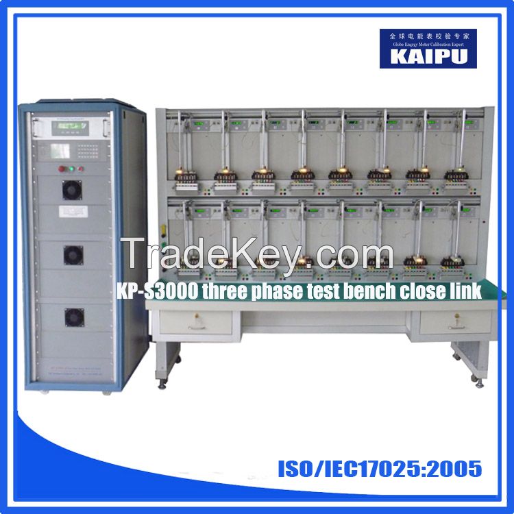
1.1
General features
The offered
universal meter testing equipment is designed for the
simultaneous testing,
adjustment and
certification of meters.
The following
electricity meters of the accuracy classes 0.2, 0.5, 1 and 2 can
be tested:
*2 wire-, 3
wire- and 4 wire meters for active and reactive
energy (true and
cross-connected),
The test system
incorporates a completely electronic test current- and test
voltage
generation. The
working standard is a wide range substandard meter directly
connected to the test circuit.
A PC system
controls the test system and supervises the test procedure. The
actual
values of test
voltage and -current and the errors of the meters under test are
displayed on the monitor. The errors of
the meters are indicated additionally on error displays at
each measuring position.
The
user software supports the following operation modes:
*Creation of type
table and test tables (sequences). Editing of already prepared
test
sequences and
type tables also possible
*Manual testing
of meter, in this case test voltage, current, PF, Frequency,
Phase
sequence,
measurement mode can be selected and set for the testing.
Operator will be
allowed to
meter constant to check the % error of meter under test.
Error results can be directly printout
*Automatic certification, using type- and test tables
*Results of
Automatic testing, Storage, printout, formatting etc.
The meters to
be tested will be suspended on a stationary meter rack
The basic
version of the test system consists of the following
components:
*1 power supply
unit , designed as **-cabinet with the modules for test
voltage and test current generation as well as the reference standard,
*1 test tables
with meter test rack for the simultaneous testing equipped
with:
Scanning
devices for rotor mark detection of inductive type meters and LED
detection ofelectronic
meters,
* IR-data heads
*1 PC system with user software
*Central error
calculator * Individual error
displays
The
test system will be connected directly to the unsterilized
mains:
**0
V (Phase to Neutral) + *0 % *- *5 %, *0 Hz ±2 %
1.2
Power supply unit
Test current
and -voltage are synthetically generated in a Fully Digital
Electronic Power
Source by the
means of a *-channel frequency generator (extendable to 8
channels) and resonant Switch Mode
Amplifiers.
These
Amplifiers have the following Characteristics:
*High
Efficiency
*DDC control by
signal processors,
*PF
compensation of the mains connection according To EN ****5 / IEC
**5
*High stability
at inductive-, capacitive-and non-linear loads
*very good
quality of the output signals, low THD
*Electronically
Protected against overload and short circuit
*Designed as
**-unit, digital controlled by fiber-optics
connection.
*Diagnostic
features in amplifier to detect the problem
The Frequency
Generator allows in combination with the wide range amplifiers
the
superposition
of harmonics.
The Closed Loop
Control conception of the frequency generator guarantees a
high
stability and
precision of test voltage and test current, in absolute value as
well as in phase
angle. The
deviation between the selected test value and the actual value is
Monitored
Continuously.
Deviations beyond the previously selected close tolerance will be
indicated
as error
message. This technology of inherent calibration guarantees the
highly precise
generation of
the output settings under all load conditions.
A malfunction
will be indicated by acoustic- and optic signal.
1.2.1
Frequency Waveform Generator
The waveform
generator is the central unit of the synthetic waveform
generation. It
generates the
set points for the digital control of the power amplifier units,
carries out the closed-loop control of the
test settings and controls changeover operations during the
test procedure. The output
settings per phase are generated with a resolution of ***0
samples per period and *6 bit in
amplitude.
The
Technical Data of the Frequency Generator are:
Test circuit
frequency computer controlled adjustable to :
*mains
synchronized operation f =*0 or *0 Hz,
*quartz
controlled operation f = *5.*0 to *5 Hz,
adjustable in
steps to 0.*1 Hz.
Test voltage
circuit Selectable in the range of
**0 to **0 V
(phase-neutral)
**0 to **8 V
(phase-phase)
*Individual
phase can be controlled
Test current
circuit Selectable in the range of
*1 mA to **0
A
*Individual
phase can be controlled
Phase
position adjustment to
any power factor
cos φ / sin φ =
0.**0 to 1.**0 in all computer controlled.
Symmetrical/Unsymmetrical
Test voltage
and current can be freely selectable as symmetrical /
unsymmetrical,
balance/unbalance
system
Superposition
of harmonics
*In the range
2nd ... *1th harmonic to each test voltage- and test current
phase individually. Two different
waveform/channel
*Magnitude of
each harmonic is adjustable over 0 ...*0 % and phase angle w.r.t
to the fundamental wave
1.2.2 Test voltage amplifier
The three - phase
test voltage amplifier is designed for generation of desired
test
parameter,
based on the command received from frequency generator
Voltage range: *0
to **0 V (phase-neutral)
*0 to **8 V (phase-phase)
Accuracy of the
test setting amplitude: 0.*5 %
Accuracy of the
test setting phase
adjustment: 0.*1°
Stability of
the output settings: < 0.*5
Distortion
factor: < 0.5 %
Superposition
of harmonics 2 to. *1. Harmonics
Output power in
the test voltage circuit: max. 3 x ***0 VA.
Protection:
Mains is
protected by Fuse and output
circuit is
Protected against short
circuit/overload
Communication:
send/receive signal through fiber optic cables.
Failure
Diagnosis feature:
Amplifier has built in self-diagnosis features, which can be activated to detect the fault inside the amplifier
1.2.3
Test current amplifier
Each of the 3
single-phase test current amplifiers is designed for:
Current range:
1mA ***0A
Accuracy of the
test setting amplitude: 0.*5 %
Accuracy of the
test setting phase adjustment: 0.*1°
Stability of
the output settings: < 0.*5
Distortion
factor: < 0.5 %
Superposition
of harmonics 2. ... *1. Harmonics
Output power in
the test current circuit: max. ***0 VA per phase
Protection:
Mains is protected by Fuse and output circuit is Protected against open circuit/overload
Communication
send/receive signal through fiber optic cables.
Failure
Diagnosis feature Amplifier has built in
self-diagnosis features, which can be
activated to detect the fault inside the
amplifier
| Pays: | China |
| N ° de modèle: | KP-S3000 |
| Prix FOB: | 1 ~ 100 / Unit Obtenir le dernier prix |
| Localité: | - |
| Prix de commande minimale: | 1 per Unit |
| Commande minimale: | 1 Unit |
| Packaging Detail: | WOODEN CASE |
| Heure de livraison: | 20 DAYS |
| Capacité de Fournir: | 100 Unit per Month |
| Payment Type: | - |
| Groupe de produits : | three phase energy meter test bench |