Description
Membrane Cleaning: Design and Operation of RO System
Clean-In-Place
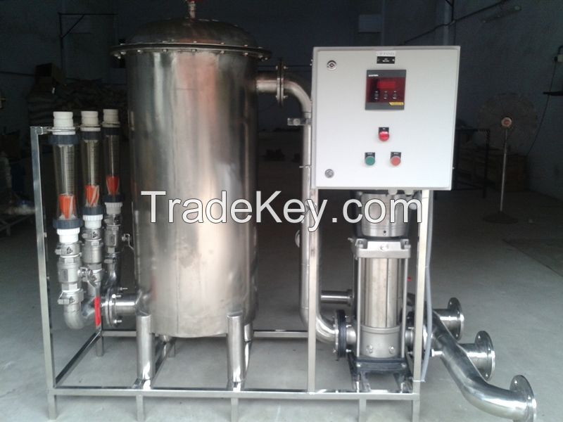
A CIP skid typically includes a tank, cleaning pump, cartridge
filter and a heating/cooling device. Figure 1 illustrates a flow
diagram of a CIP system.
The CIP system is connected with the RO system either with flexible
hoses or fixed piping (stainless steel or FRP). Large RO systems
typically have fixed piping since the cleaning flow quantities are
such that flexible hoses shouldn\'t be used either due to handling
issues (heavy) and/or safety reasons.
The materials used for the CIP system should withstand a pH range
of ***3 and temperatures up to **2F (*0C). They should be
non-corrosive.
Flat bottom tanks aren\'t recommended since it isn\'t possible to
drain these tanks completely. The residual amount of liquid
remaining in the tank becomes more contaminated over time. The
cleanings will become less effective since fresh cleaning solution
is contaminated with the residual liquid. In addition, the
contaminated cleaning solution may cause a decline of the membrane
element performance since additional foulant is introduced into the
RO system.
Conclusions:
The design of the clean-in-place skid and the integration with the
reverse osmosis system is important to obtain good cleaning results
and subsequently increase the lifetime of reverse osmosis membrane
elements.
What to do with an existing system that does not have a properly
designed CIP system? One can make modifications to the
clean-in-place skid.
