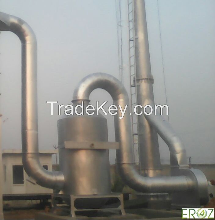
Air Pollution Control Device for Steel Rolling Mills By Eroz Environ Engineer Pvt. Ltd.,
Pas encore membre de TradeKey.com? Inscrivez-vous pour vous connecter avec 9 millions d'importateurs et exportateurs. Rejoignez-le maintenant c'est gratuit |
BOOK A CALL
Book Call On Your Favorite Time

By Signing Up. I agree to TradeKey.com Terms of Use, Privacy Policy, IPR and receive emails related to our services

Contact Us
product
Prev
Air Pollution Control Device for Steel Rolling Mills
Next

Air Pollution Control Device for Steel Rolling Mills

|

1 Set Minimum Order

Pays:

India

N ° de modèle:

APCDSRM1

Prix FOB:

Localité:

-

Prix de commande minimale:

-

Commande minimale:

1 Set

Packaging Detail:

export worthy

Heure de livraison:

4 to 6 weeks

Capacité de Fournir:

-

Payment Type:

T/T

Groupe de produits :

Contacter maintenant
Membre gratuit

Personne à contacter Mr. Capt Anil Kumar

25-D, Industrial Growth Centre, Mansa Road, Bathinda, Punjab

Contacter maintenant

Spécification du produit

  • Parameters:Dust/Gas Concentration at inlet, Discharge Standards, Temper

La description

Product Details
Air Pollution Control Device for Steel Re-rolling Mill (Secondary recycling of Steel)

About Steel re-Rolling Mill

Steel Re-rolling is a major steel section and bar producing technology used in India and abroad. Since its inception in India with setting up of first re-rolling mill in Kanpur in ***8, this technology has contributed significant steel making capacity in secondary steel sector in India.

It has some distinct Advantages :

1 Low Project Capital Cost
2 Low Fuel efficiency
3 Provides choice to end user with variety of product at lower cost.
4 Can be set up near source which saves transportation cost of raw material.

Manufacturing Process

Steel re-rolling process starts with cutting of billets in desired lengths. These are then loaded at pusher platforms from where they are pushed into the furnace. The Furnace may be coal fired, oil fired or even gas fired. In the furnace, billets are heated up
0 to ***0 C and they become red hot for further rolling process which now consists of stage wise rolling of steel. They are transported to rolling stands and rolled into desired shapes. The rolled structure is then cooled and taken to the yard. Flue
gases are generated during heating of billets in the furnace. The characteristics and volume of these gases mainly depends upon type of fuel used in the furnace. These flue gases need proper treatment for removal of dust particles/gases before being
discharged into the atmosphere.

Air Pollution

Depending upon the fuel used in heating the furnace of a Steel Re-rolling Mill, the characteristics of flue gases may vary. For coal fired furnaces they may consist of gaseous as well as particulate pollutants. For oil or gas fired furnaces, these
flue gases may consist of just gaseous pollutants. The flue gases may also be corrosive in nature.

Capacity Calculation of required Equipment for Air Pollution Control Device

The volumetric capacity of Air Pollution cannot be judged as such, but fair engineering estimation can be made with data like :

1 Furnace Capacity
2 Fuel Consumption

Characteristics of Air Pollution Generated In Induction Furnace

1 Pollutants : Dust & Gases such as NO , SO , CO, Co x 2 2
2 Concentration : SPM - ********0 mg/Nm (Maximum, in coal fired)
3 So - *******0 mg/Nm 2
4 NO - ****0 mg/Nm x
5 Temperature : At Suction Point: ******0 C
6 Nature of Dust : Slightly Sticky, Non Abrasive and Non Explosive

Control Practices

The control practice adopted in controlling air pollution in this industry mainly depends upon following parameters :

1 Dust/Gas Concentration at inlet
2 Discharge Standards
3 Temperature of Flue Gases
4 Nature of Pollutant i.e. Dust (Particulate) or Gaseous
5 Nature of Dust i.e. Sticky, Abrasive
6 Nature of Gases i.e. Corrosive, Non Corrosive

Selection of Technology for Air Pollution Control Device

Selection of Technology for Equipment in an Air Pollution Control System in case of a Steel Re-rolling Mill depends upon the fuel to be used :

a. Scrubber based System for Oil / Gas Fired Furnaces
b. Cyclone and Scrubber based System for Coal Fired Furnaces

About Scrubber based System for Oil / Gas Fired Furnaces

Working of Equipment

1. Ducts & Bends :

Ducts and Bends are required to convey flue gases from point of suction to the chimney and connect various equipments like Scrubber, ID Fan and Chimney. Their sizes are based on flue gases volume & temperature. A Damper is
usually provided at the suction point.

2. Scrubber :

A Wet Scrubber is provided for treatment of gases in an Oil / Gas fired Re-rolling Furnace. In a Wet Scrubber the flue gases are introduced from side entrance at near the bottom of the shell. Then water is pumped from the storage tank below the scrubber and is sprayed from the top through a sprinkler arrangement. Flue Gases move through the contact plate where the wetted dust particles settle. As the flue gases move up the scrubber, pollutants such as CO , SO & NO get 2 2 x absorbed in water. Cleaned Flue Gases then move up and after passing through a mist eliminator where moisture in gases is removed, exit the scrubber.

The dust as well as the gaseous pollutants are carried to the bottom tank with water. Here a dose of caustic / lime is provided to maintain the pH of the water. A three portioned tank also allows for settling of suspended solids in water which are then
periodically cleaned and stored in HDPE bags in accordance with Hazardous Waste Management Rules. (Larger units may need separate Effluent Treatment Plants to properly treat water for re-circulation)

3. ID Fan :

ID Fan provides necessary driving force to convey flue gases from suction point to top of the chimney. The volume sucked overcomes the total resistance offered by equipment and duct with the help of fluid horse power provided by ID Fan driven by suitable motor.

4. Stack (Chimney) :

The generated gases are passed through chimney of suitable height and diameter. The chimneys are provided and based on volume of flue gases, temperature, dispersion desired, composition of gases and legal provisions for
height.

About Cyclone and Scrubber based System for Coal Fired Furnace

Working of Equipment

1. Ducts & Bends :

Ducts and Bends are required to convey flue gases from point of suction to the chimney and connect various equipments like Cyclone, Scrubber, ID Fan and Chimney. Their sizes are based on flue gases volume & temperature. A Damper
is usually provided at the suction point.

2. Cyclone :

A high efficiency Cyclone separator is provided to capture dust particles. Flue gases after cooling in a Heat Recovery Unit are introduced in a tangential entry in the multiple tubes of the involute cyclone. Due to centrifugal forces dust particles settle at the bottom cones while flue gases exit the cyclone through the center tube. Collected dust particles are periodically removed.

3. Scrubber :

A Wet Scrubber is provided for treatment of gases in an Oil / Gas fired Re-rolling Furnace. In a Wet Scrubber the flue gases are introduced from side entrance at near the bottom of the shell. Then water is pumped from the storage tank below the scrubber and is sprayed from the top through a sprinkler arrangement. Flue Gases move through the contact plate where the wetted dust particles settle. As the flue gases move up the scrubber, pollutants such as CO , SO & NO get absorbed in 2 2 x
water. Cleaned Flue Gases then move up and after passing through a mist eliminator where moisture in gases is removed, exit the scrubber.

The dust as well as the gaseous pollutants are carried to the bottom tank with water. Here a dose of caustic / lime is provided to maintain the pH of the water. A three portioned tank also allows for settling of suspended solids in water which are then
periodically cleaned and stored in HDPE bags in accordance with Hazardous Waste Management Rules. (Larger units may need separate Effluent Treatment Plants to properly treat water for re-circulation)

Note: Due to continuous up-gradation in technology, specified & projected values may differ in actual products.

4. ID Fan :

ID Fan provides necessary driving force to convey flue gases from suction hood to top of the chimney. The volume sucked overcomes the total resistance offered by equipment and duct with the help of fluid horse power provided by ID Fan driven by suitable motor.

5. Stack (Chimney) : The generated gases are passed through chimney of suitable height and diameter. The chimneys are provided and based on volume of flue gases, temperature, dispersion desired, composition of gases and legal provisions for
height.

Discharge Characteristics as Per Norms

1 Dust : Less than **0 mg/ Nm
2 Temp : Less than *****0 C
3 Gases : Traces of SO , NO , Co , Co

Pays: India
N ° de modèle: APCDSRM1
Prix FOB: Obtenir le dernier prix
Localité: -
Prix de commande minimale: -
Commande minimale: 1 Set
Packaging Detail: export worthy
Heure de livraison: 4 to 6 weeks
Capacité de Fournir: -
Payment Type: T/T
Groupe de produits : Air Pollution Control Device

Send a direct inquiry to this supplier

To:

Mr. Capt Anil Kumar < Eroz Environ Engineer Pvt. Ltd. >

Je veux savoir: